

The disassembly and maintenance steps of automobile suspension.
The Above Is The Disassembly And Assembly Of Volkswagen's Front Suspension As An Example:
1. Remove the wheel trim cover.
2. Remove the fastening nut between the hub and drive shaft when the wheel is on the ground, and remove the wheel.
3. Remove the brake caliper and brake disc; Remove the brake hose bracket and wire the brake caliper assembly to the body, taking care not to remove or damage the brake hose.
4. Remove the fastening bolts between the shell of the shock absorber pillar and the hub.
5. Press the tie rod connector from the shock absorber strut housing with a puller.
6. Remove the stabilizer bar and nuts on the drive shaft and hub from below the swing arm. Drop pressure on the front suspension swing arm and pull out the drive shaft from the wheel bearing. If not out, available pressure out.
7. Remove the cover, support the lower part of the shock absorber pillar, fix the slide column with special tools, and remove the nut on the shock absorber. The spring - loaded shock absorber assembly can be removed.
8. Disassemble shock absorber assembly with spring, press spring, nut and nut cover with wrench and special tool slot. Remove the spring.
9. Clamp knuckle arm on bench pliers. Remove the shock absorber mounting nut and pull out the front shock absorber.
10. Press out hub bearings. Remove the brake disc, remove the fender, press out the hub, remove the retaining ring from the strut housing, press out the hub bearing in the direction of the retaining ring, and pull out the bearing inner seat ring with a puller.
For Example, The Disassembly Of Jetta's Front Suspension:
(1) Disassembly of wheel and steering knuckle
1) Loosen the tire bolts
2) Remove the wheel
3) Remove the front brake
4) Separate steering knuckle from front shock absorber
5) Remove knuckle
(2) decomposition of steering knuckle
1) Remove the bearing inner ring from the wheel shaft
2) Remove bearing from steering knuckle
(3) The removal and decomposition of the front shock absorber
(4) Disassembly and decomposition of trapezoidal arm
1) Remove the trapezoidal arm
2) Take out the front and back bushings of the trapezoidal arm
(5) Disassembly and decomposition of universal joint shaft
1) Remove the universal joint from the vehicle
2) Decomposition of universal joint shaft: remove the outer constant velocity universal joint cover, remove the outer constant velocity universal joint, remove the inner constant velocity universal joint, and press out the vibration buffer of the universal joint shaft.
3) Decomposition of the external constant velocity universal joint: the disassembly of the mark and the steel ball before the disassembly of the external constant velocity universal joint, the disassembly of the external constant velocity universal joint cage and the ball yi, the separation of the external constant velocity universal joint cage and the ball yi.
4) Decomposition of the internal constant velocity universal joint: disassemble the steel ball of the internal constant velocity universal joint and disassemble the internal constant velocity universal joint for perseverance.
Installation Of Jetta Front Suspension:
Installation is carried out in the reverse order of disassembly, but the following matters must be noted:
Installation of auxiliary frame, transverse stabilizer bar and trapezoidal arm: assembly of trapezoidal arm front bushing, assembly of trapezoidal arm rear bushing, installation of auxiliary frame, trapezoidal arm and lower ball hinge, installation of transverse stabilizer bar.
Steering knuckle and wheel assembly: installation of steering knuckle bearings.
Installation of steering knuckle and front shock absorber: assembly of steering knuckle and front shock absorber, installation of steering knuckle and trapezoidal arm, installation of front shock absorber
Assembly Of Universal Joint:
Assembly of external constant velocity universal joint.
Assembly of internal constant speed universal joint: installation of ball yi, installation of steel ball and protection frame, cage installation.
Assembly of universal joint shaft: assembly of outer constant velocity universal joint and universal joint circumference, installation of vibration buffer, assembly of inner constant velocity universal joint and universal joint shaft, installation of inner constant velocity universal joint shield.
Installation of universal joint shaft: installation of universal joint shaft and driving flange of main reducer, installation of universal joint and wheel, check the clearance of wheel bearing.
Wheel installation: brake caliper and brake disc installation, wheel installation.
Measurement And Adjustment Of front Wheel Positioning Angle
(1) Measurement of front wheel Angle
(2) Measurement and adjustment of front wheel positioning Angle
1) Check the conditions
2) Measurement and adjustment of front bundle
3) Measuring and adjusting wheel camber
4) Kingpin camber and camber Angle adjustment
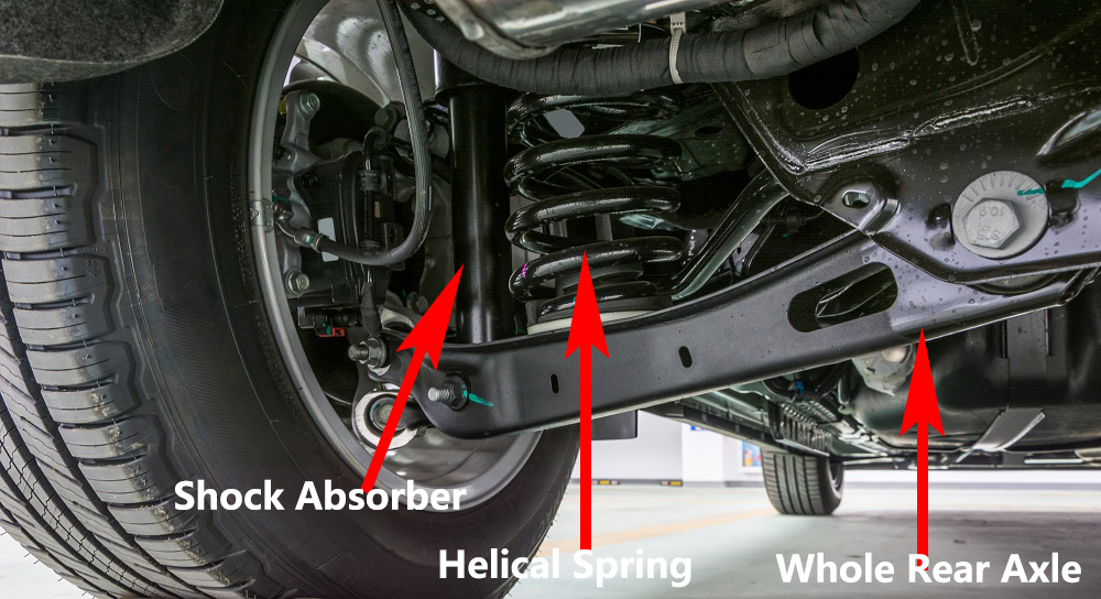
Automobile Rear Suspension Installation
Installation Is Carried Out In The Opposite Order From Disassembly, But It Is Necessary To Pay Attention To The Following Matters:
(1) The assembly and installation of the rear bridge body: the rubber support of the rear bridge body, the installation bracket and the rear bridge body, the installation of the rear bridge body.
(2) Assembly and installation of rear shock absorbers
1) Install rear shock absorbers
2) Connect the rear axle body with the rear shock absorber
(3) Installation of short shafts and bearings
1) Install the outer ring of the brake drum outer ring conical roller bearing
2) Install the outer ring of the cone roller bearing of the inner ring of the brake drum
3) Install the brake drum oil seal
4) Install the short shaft
5) Install brake drum
6) Adjust the preload of the bearing wheel
7) Install the locking universal cotter pin
8) Install grease cover
(4) Check the positioning Angle of the rear wheel
1) Check the camber of the rear wheel
2) Check the front harness of the rear wheel
The Disassembly And Assembly Of Automobile Suspension Matters Needing Attention
(1) The front suspension assembly cannot be welded and repaired.
(2) The self-locking nut must be replaced with a new one.
(3) The tightening torque of nuts or bolts should meet the requirements.
(4) The hub bearing should be coated with grease before pressing in, and the opening position of the two retaining rings differs 180.
(5) For hydraulic steering, in the drive shaft spline to apply 5mm wide sealant,60 minutes before driving.
We will do a good job in every content,do our best to solve the problem for each customer,Thank you for your reading.
Leave A Comment